
Temperature Measurement in Process Industry
Introduction to temperature measurement
Temperature measurement is a critical parameter in virtually every process industry. From chemical plants and refineries to food processing and pharmaceuticals.
Temperature is not measured directly. We always have to measure something else, which is proportional to a certain temperature. There are many methods; RTD (Resistance Temperature Device), TC (Thermo Couple), Pyrometers, IR meters, Distributed Temperature Sensing Systems (DTS), etc.
Here we will mainly focus on RTD (pt100 elements) and TC (Thermo Couple) in this article.
What is a temperature transmitter?
Temperature transmitters take the readings from temperature sensors (like thermocouples or RTDs) and turn them into stronger, more reliable signals (usually 4-20 mA or digital) that can be used by other control equipment. They improve accuracy by boosting the signal, filtering out noise, correcting for any non-linearities, and often providing isolation.
Resistance Temperature Detectors (RTDs) or pt-100
Pt is the abbreviation for the metal platinum. This is a fine, expensive, and noble metal
with clearly defined properties. We machine this platinum wire so that the electrical
resistance value, when the temperature is 0 degrees Celsius, is exactly 100 ohms. Hence
the name pt-100. The most commonly used in industry is the Pt-100 element.
A Resistance Temperature Detector (RTD) or pt-100
element is a temperature sensor
that exhibits the physical property of changing its resistance with temperature.
The platinum wire has the property that for every degree Celsius the temperature changes,
the electrical resistance changes by approximately 0.385 ohms. If the temperature rises,
the resistance rises. And if the temperature falls, the resistance falls. There is an almost
perfect linearity between temperature and resistance value. The International
Electrotechnical Commission (IEC) has created a standard that accurately describes
the relationship (IEC 60751: Industrial platinum resistance thermometers and platinum
temperature sensors).
There are 2 types of "robustness" for these as defined by IEC 60751: "wire sensor"
suitable for
applications with large variations or shock changes in temperature, and "thin film"
which has a fast response time and is very resistant to vibration. The "wire sensor"
is commonly used in industry. Furthermore, there are typically 2 solutions used in
industry:
Solutions:
- 2-Wire Solution: Simplest, but susceptible to errors due to the resistance of the connecting wires influencing the measurement. The simplest and most cost-effective option, suitable for short distances where the resistance of the connecting wires does not significantly affect accuracy. It's commonly used in industrial applications where high precision is not critical.
- 3-Wire Solution: Compensates for wire resistance by subtracting supply cable resistance, with error limited to differences between the three wires. The three-wire configuration effectively minimizes the influence of lead wire resistance, which can introduce significant errors in temperature readings. This configuration is particularly valuable for applications requiring high accuracy over moderate distances.
- 4-Wire Solution: Eliminates systematic errors by measuring all wire resistances, enabling highly accurate sensor measurements. The four-wire configuration achieves the highest accuracy by completely eliminating the influence of lead wire resistance. This method is ideal for demanding applications requiring the utmost precision, such as laboratory environments and critical processes.
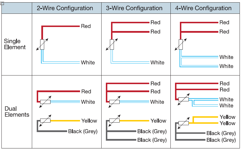
What is the difference between simplex and duplex RTD's
Duplex temperature sensors (dual element thermocouple) consist of a pair of temperature sensors within a single enclosure. For example, a duplex thermocouple would have two pairs of thermocouple conductors in a single sheath. Similarly, a duplex RTD sensor would have two RTD/pt100 elements at its hot end instead of a single element. The main reason for a dual thermocouple probe configuration is to enable redundancy if one of the sensors fails. Duplex sensors cost more, but certain applications benefit from the redundancy gained. Peak Sensors can make all designs of duplex sensor, both duplex thermocouples and duplex pt100 sensors
1. Head mounted temperature transmitters
These are compact transmitters that fit inside the connection head of a temperature sensor. They are easy to install and minimize wiring.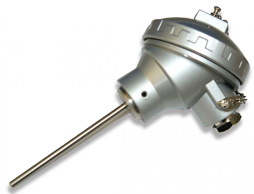

2. DIN rail/panel mounted temperature transmitters
These are designed to be mounted on a DIN rail inside a control cabinet or panel. They are commonly used in industrial applications due to their versatility and cost-effectiveness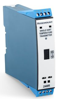
3. Field mounted temperature transmitters with display
These transmitters are housed in rugged enclosures suitable for direct installation in the process environment. They are often weatherproof and sometimes explosion-proof for hazardous locations.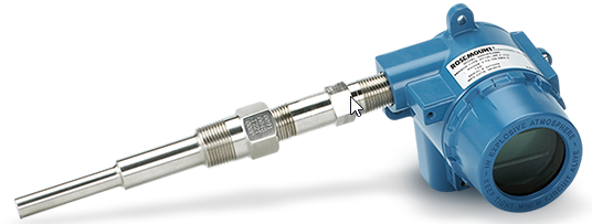
4. Direct Connection to PLC (no transmitters needed)
It's also possible to connect temperature sensors directly to a PLC (Programmable Logic Controller). Instead of using a transmitter to convert the signal, the sensor (thermocouple or RTD) is wired directly to an input card on the PLC. These input cards are specifically designed to handle the low-level signals from these sensors.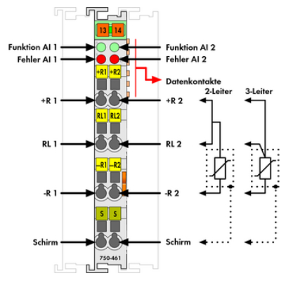
Accuracy and sensitivity
For Pt100 elements, these polynomials are used to describe the relationship between temperature and resistance:- For temperatures from \(-200\,℃ \leq t \leq 0\,℃\): \[ R_t = R_0(1 + At + Bt^2 + C(t - 100)t^3) \]
- For temperatures from \(0\,℃ \leq t \leq 850\,℃\): \[ R_t = R_0(1 + At + Bt^2) \]
where, \[ A = 3.9083 \times 10^{-3},\quad B = -5.775 \times 10^{-7},\quad C = -4.18 \times 10^{-12} \]
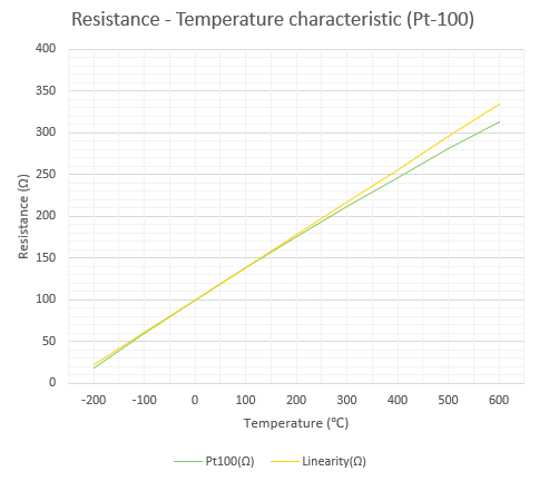
The equation for linearity is as follows (See table 2 - Linearity):
\[ R = R_0(1 + a_1T) \] ,where a1 is the constant 3.9083 × 10⁻³ , R0 is the resistance at 0℃ and T is the temperature.
The temperature coefficient is calculated as follows:
\( α = \frac{(R_{100} - R_0)}{(R_0 \cdot \text{Temp})} \)
Where R100 is the resistance at 100℃, R0 is the resistance at 0℃ and Temp is the temperature
| Coefficient (α) | R100(Ω) | Temp (°C) | R0 (Ω) |
|---|---|---|---|
| 0.00385055 | 138.51 | 100 | 100 |
Table 1 - Table for calculated coefficient for pt100 element (formula 2. above)
| Temperatures (℃) | -200 | -100 | 0 | 100 | 200 | 300 | 400 | 500 | 600 |
|---|---|---|---|---|---|---|---|---|---|
| Pt100 (Ω) | 18,52 | 60,26 | 100,00 | 138,51 | 175,86 | 212,05 | 247,09 | 280,98 | 313,71 |
| Linearity (Ω) | 21,83 | 60,92 | 100 | 139,08 | 178,17 | 217,25 | 256,33 | 295,42 | 334,50 |
| Deviation(Ω) | 3,31 | 0,66 | 0,00 | 0,58 | 2,31 | 5,20 | 9,24 | 14,44 | 20,79 |
Table 2 - table for calculating deviations to pt 100 element and calculating how the linearity should be
Standards
Ranges are defined by "The International Scale" (ITS-90) from -259°C to +962°C, while ASTM has defined somewhat "narrower" limits, -200°C to +650°C which has become the industry standard even though IEC has up to 850°C as an acceptable measurement range, but IEC does not cover temperatures above 600°C.
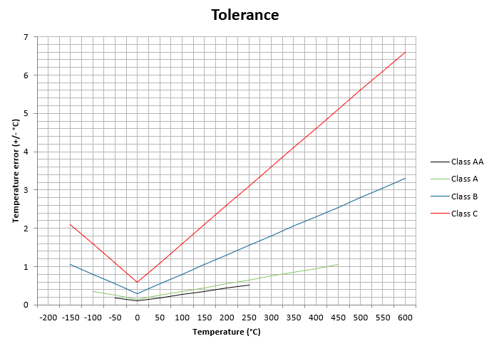
Tolerance
Due to manufacturing variations and other factors, there's a degree of variability in the actual resistance of a Pt100 sensor. This variability is defined by its tolerance.| Class | Wire sensor | Film sensor | RTD Tolerance in °C | |||
|---|---|---|---|---|---|---|
| AA | -50 | +250 | 0 | +150 | +/-(0,1 + 0,0017 |t|) | |
| A | -100 | +450 | -30 | +300 | +/-(0,15 + 0,002 |t|) | |
| B | -196 | +600 | -50 | +500 | +/-(0,3 + 0,005 |t|) | |
| C | -196 | +600 | -50 | +600 | +/-(0,6 + 0,01 |t|) | |
Table 3 - Table from IEC 60751:2008 (Industrial platinum resistance thermometers and platinum temperature sensors)
|t| = absolutt RTD temperatur i °C
Self-heating
The Pt-100 element is a passive device, meaning it does not generate its own voltage. Therefore, an external voltage source is required to measure the change in resistance. To prevent self-heating and ensure accurate measurements, the excitation current must be kept at a low level. For applications demanding extreme precision, the self-heating effect must be carefully calculated and accounted for.
Signal transmission
Traditionally, compensation for lead wire resistance in Pt-100 measurements was achieved using cables with conductors exhibiting similar temperature coefficients to the Pt-100 element itself. However, modern Pt-100 sensors often incorporate integrated electronics within the sensor head, providing real-time compensation for lead wire resistance.