
Basic Measurement Concepts
Select a topic heading to view its detailed content
1. Introduction to industrial instrumentation
Industrial instrumentation is the cornerstone of modern process control and automation, serving as the eyes, ears, and hands of industrial operations. This chapter introduces the fundamental concepts, components, and principles that form the foundation of industrial instrumentation systems.
The Role of Instrumentation in Industry
Industrial instrumentation encompasses the measurement, control, and monitoring of physical processes in manufacturing and production environments. From chemical processing plants to power generation facilities, instrumentation systems enable operators to:
- Monitor process variables such as temperature, pressure, flow, and level
- Maintain product quality through precise control
- Ensure safe operation of equipment and processes
- Optimize resource utilization and energy efficiency
- Record and analyze process data for continuous improvement
Measurement Fundamentals
Understanding measurement principles is crucial for proper instrument selection and application: Accuracy and precision requirements Range and span considerations Static and dynamic response characteristics Environmental factors and installation requirements
Industry Standards and Safety
Industrial instrumentation must comply with various standards and practices:
- Safety Standards
- Industry-Specific Standards
IEC 61508 for functional safety ATEX and IECEx for hazardous area protection Safety Integrity Level (SIL) requirements
ISA standards for instrumentation practices API standards for oil and gas applications FDA requirements for pharmaceutical manufacturing
Future Trends
The field of industrial instrumentation continues to evolve with:
- Industrial Internet of Things (IIoT) integration
- Wireless instrumentation technologies
- Smart sensors with self-diagnosis capabilities
- Advanced analytics and predictive maintenance
- Digital twins and virtual sensing
Conclusion
Industrial instrumentation forms the foundation of process automation and control.
Understanding its principles, components, and applications is essential for
engineers and technicians working in industrial environments. This knowledge
enables the design, implementation, and maintenance of reliable and efficient
control systems that drive modern industrial processes.
The following chapters will delve deeper into specific aspects of industrial
instrumentation, providing detailed information about sensor technologies,
signal processing, control strategies, and practical applications in various
industries.
2. Instrumentation Variables Explained: A Comprehensive Guide to Process Values, Ranges, etc
In the world of industrial instrumentation, understanding measurement variables and
their relationships is fundamental to effective process control and monitoring.
Whether you're working with pressure transmitters, temperature sensors, or flow
meters, these concepts remain consistent across different types of instrumentation.
Every measurement device operates within specific boundaries and conditions.
These boundaries are defined by various range concepts.
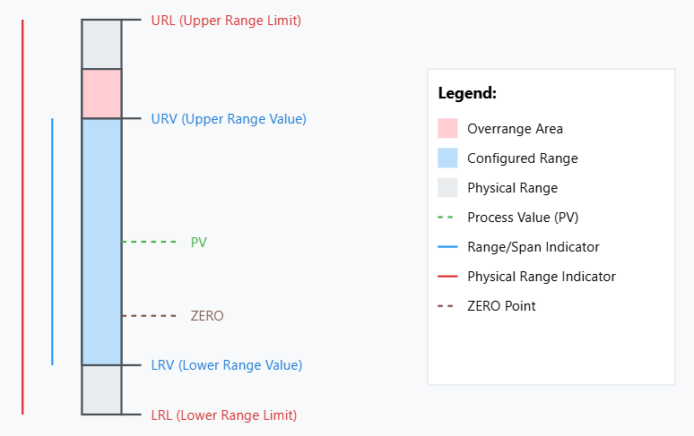
We'll explore essential instrumentation variables that every technician, engineer,
and operator should understand. A diagram illustrating these concepts follows below.
- Process Value (PV): This is the actual measurement being read by the instrument in real-time. It's the live reading that shows what's happening in the process right now. This value will be moving accordingly to the process.
- Lower Range Limit (LRL): This is the absolute lowest value that the instrument can physically measure. It's a hardware limitation built into the device that cannot be changed. This is the lowest measurement variable the instrument can be adjusted to measure.
- Upper Range Limit (URL): This is the absolute highest value that the instrument can physically measure. Like the LRL, it's a hardware limitation that's built into the device and cannot be changed. This is the highest measurement variable the instrument can be adjusted to measure.
- Lower Range Value (LRV): This is the lowest value of the configured measurement range. Users can set this value anywhere between the LRL and URL. It typically corresponds to 0% of the output signal (often 4mA in a 4-20mA system).
- Upper Range Value (URV): This is the highest value of the configured measurement range. Users can set this value anywhere between the LRL and URL. It typically corresponds to 100% of the output signal (often 20mA in a 4-20mA system).
- Range: This is the span of values between the LRV and URV. It represents the configured working range of the instrument where it provides its specified accuracy.
- Span: This is the mathematical difference between URV and LRV. For example, if LRV is 20 PSI and URV is 100 PSI, the span is 80 PSI. It's same as the calibrated measurement range.
- ZERO: This is a reference point that can be set anywhere within the configured range. It doesn't necessarily have to be at the LRV or at actual zero. It's used as a calibration reference point.
- Overrange: This is the condition when the Process Value exceeds the URV but remains below the URL. The instrument continues to measure, but may have reduced accuracy.
- Overrange Limit: This is the maximum safe value beyond the URV that the instrument can measure without damage. Exceeding this limit risks damaging the instrument.
Practical Example 1:
- Consider a temperature transmitter:
- Physical limits: LRL = -50°C, URL = +250°C
- Configured range: LRV = -20°C, URV = +200°C
- Span: 220°C
- ZERO might be set at +20°C
- Overrange occurs between 200°C and 250°C
- Overrange Limit might be set at 230°C for safety
Practical Example 2:
Let me illustrate this with another practical example: Consider a pressure transmitter with physical limits (LRL to URL) of -100 to +400 PSI. It might be configured with an LRV of 0 PSI and URV of 200 PSI, giving a span of 200 PSI. The ZERO point could be set to atmosphere pressure (14.7 PSI). If the pressure rises above 200 PSI (URV), but stays below 400 PSI (URL), the transmitter is in overrange condition. The overrange limit might be set at 300 PSI to protect the instrument.
Advertisement
Get 20% discount on hostinger. Click the link
3. Measurement units and SI system
The International System of Units (SI) is the modern form of the metric system. It is the world's most widely used system of measurement, used in science, technology, industry, and commerce.
Measurement Units
Physical quantities require standardized units for consistent measurement. Common types
include base units and derived units, with prefixes (kilo-, milli-, etc.) indicating scale.
The derived units in SI, such as pascals for pressure or watts for power, are combinations
of base units that maintain mathematical consistency throughout calculations. This consistency
is particularly valuable in complex engineering systems where multiple physical quantities
interact
Fundamental SI Units
The International System of Units, or SI, defines seven base units. All other SI units are derived from these base units. The SI base units are used in all fields of science and technology, and they are essential for ensuring that measurements are accurate and consistent
| Physical Quantity | Unit | Symbol |
|---|---|---|
| Length | meter | m |
| Mass | kilogram | kg |
| Time | second | s |
| Electric Current | ampere | A |
| Temperature | kelvin | K |
| Amount of Substance | mole | mol |
| Luminous Intensity | candela | cd |
6. Signal types (4-20mA, 0-10V, HART, digital signals) and signal processing
4-20mA current signal
The 4-20mA current signal is the most widely used analog signal standard in industrial instrumentation and process control. This current loop system operates by varying the current between 4mA (representing 0% or the minimum value) and 20mA (representing 100% or the maximum value) to transmit process measurements.
The 4-20mA standard offers several key advantages that make it ideal for industrial applications. First, using 4mA as the zero point instead of 0mA enables the system to detect signal failures or broken wires, as any current below 4mA indicates a fault condition. The current-based nature of the signal makes it highly resistant to voltage drops and electrical noise over long transmission distances, as the current remains constant throughout the loop regardless of cable resistance.
The signal operates on a two-wire system, where the same pair of wires carries both the power supply and the measurement signal. This reduces installation costs and complexity compared to voltage-based systems that require separate power wires. The transmitter regulates the current draw from the power supply (typically 24VDC) to represent the measured value, while the receiver measures this current to determine the process value.
The relationship between measurement range and signal range can be expressed as follows:
See also my calculator for this here
0-10V signal type
The 0-10V signal type is a fundamental analog voltage signal used extensively in industrial instrumentation and automation systems. In this configuration, 0V represents the minimum value or 0% of the measured parameter, while 10V indicates the maximum value or 100%, with all values in between representing proportional measurements.
While 0-10V signals offer advantages such as simple implementation, good noise immunity, and wide compatibility with industrial equipment, they do have limitations including voltage drop over long distances and susceptibility to electromagnetic interference compared to current-based signals.
Hart
The HART (Highway Addressable Remote Transducer) protocol is a hybrid communication system that combines digital communication with traditional 4-20mA analog signals in industrial instrumentation. The protocol works by superimposing a digital signal on top of the standard 4-20mA analog signal, allowing bidirectional communication while maintaining compatibility with existing analog systems.
The signal processing capabilities of HART include: Advanced diagnostics that can detect sensor failures, calibration problems, or configuration errors. Remote device configuration allows operators to adjust parameters without physically accessing the device. Multi-variable measurements enable a single transmitter to communicate multiple process variables digitally while still maintaining the analog measurement of the primary variable.
Some limitations to consider are:
The relatively slow communication speed compared to purely digital protocols. The need for
HART-compatible receiving equipment to access digital features. Potential interference from
nearby electrical equipment that can affect digital communication quality.
Digital signals
Digital signals in PLCs (Programmable Logic Controllers) serve as the fundamental communication method for industrial automation and control systems. These signals operate in a binary format, where inputs and outputs can be either ON (1/True/24V) or OFF (0/False/0V), making them ideal for controlling discrete processes and reading binary sensor states.
Input digital signals to a PLC come from various field devices including: Push buttons transmit operator commands as simple ON/OFF signals. Limit switches indicate position status of machinery or equipment. Proximity sensors detect the presence or absence of objects. Photoelectric sensors detect objects using light beams. Temperature switches provide binary feedback when temperatures exceed preset limits.
Output digital signals from PLCs control devices such as: Relays switch larger electrical loads based on PLC logic. Solenoid valves control pneumatic or hydraulic systems. Motor starters activate or deactivate motors. Indicator lamps provide visual status information. Alarm systems alert operators to specific conditions.